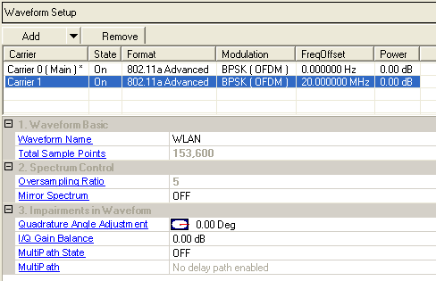

This table enables you to view the key parameters for each carrier in the waveform. You can also add or delete carriers using the buttons above the table (see descriptions below). Double-clicking a carrier row activates the setup tables for that carrier. You can use a maximum of 5 carriers.
 The button
opens a drop-down menu for selecting a carrier to add to the setup table.
The carrier has either Basic capability or Advanced capability.
 The
button deletes the currently highlighted carriers in the setup table.
You can highlight multiple carriers by holding down the CTRL
key while selecting the carriers. You can also use the SHIFT key to select
a succession (group) of carriers.
Use this cell to enter a name for the waveform. The alphanumeric text entered in this cell appears in the signal generator's user interface after the configuration is downloaded to the instrument. The signal generator recognizes only waveform names that use the following characters:
A through Z
0 through 9
$ & _ # + - [ ]
If unsupported characters appear in a configuration name, the signal generator generates a error (Error: -256) when you download the configuration to the instrument. The maximum length for file names is 22 characters.
Enter an alpha-numeric comment of up to 32 characters. The comment resides in the file header and can include spaces and special characters.
This cell displays the number of samples (or data points) in the waveform. The number of sample points varies with the Oversampling Ratio and is related to the number of packets, the frame mode, the data rate, and the length of the user data. The maximum number of samples a waveform can have depends on the ARB memory capacity of the signal generator's baseband generator. You cannot edit cells in this column. This total samples value also appears in the status bar at the bottom of the main window.
Use this cell to specify the number of times that the baseband signal is oversampled. The minimum value of this cell is 2.
For 802.11b and 802.11g DSSS mode, the maximum value is 116.
For 802.11j/p with 10 MHz bandwidth, the maximum value is 128.
For 802.11a, 802.11j/p with 20 MHz bandwidth and 802.11g OFDM modulation, the maximum value is 64.
For 802.11p 5-MHz mode, the maximum value is 256.
Use this cell to set the mirror spectrum to either ON or OFF.
As a signal propagates normally through the different functional blocks of a receiver (for example, the mixer block), the signal spectrum may be inverted. Enabling this cell facilitates realistic testing of receiver functional blocks that would normally be presented with a mirrored spectrum signal. The default setting is OFF.
ON: When this cell is set to ON, the Q channel is inverted, resulting in a mirrored spectrum
OFF: When this cell is set to OFF, the spectrum is not inverted.
Use this cell to add quadrature skew impairment (-90 to + 90 degrees) to the generated waveform. This affects the waveform data so it applies to both RF and baseband I/Q outputs.
The baseband Quadrature Angle (angle) and the baseband IQ Gain (gain) values are used to modify the output I and Q data according to the following equations:
Real (output) = Real (input) - Gs * Imag (input)
Imag (output) = Gc * Imag (input)
where:
Gs = Gain * sin (angle) and
Gc = Gain * cos (angle)
Use this cell to add quadrature gain impairment (-10 dB to 10 dB) to the generated waveform. This affects the waveform data so it applies to both the RF and baseband I/Q outputs.
Use this cell to enable or disable the Multipath configuration.
The ![]() Multipath
menu enables you to add up to 20 paths with delay, attenuation, and phase
impairments to simulate the multipoint reflection experienced in a real-world
WLAN multipath environment. The editing table was designed so that the
user can randomly edit and enable or disable paths as needed for fine-tuning.
Multipath
menu enables you to add up to 20 paths with delay, attenuation, and phase
impairments to simulate the multipoint reflection experienced in a real-world
WLAN multipath environment. The editing table was designed so that the
user can randomly edit and enable or disable paths as needed for fine-tuning.
The following impairments can be made to each path:
Delay (0 to 10 ms) - A reflected signal bounces off of one or more surfaces before reaching the receiver, resulting in a longer path than the line-of-sight signal. Therefore, the reflected signal experiences some amount of delay, relative to the line-of-sight signal. Since WLAN signals travel short distances, path delays are usually small (nanoseconds)
Attenuation (0 to 60 dB) - Attenuation occurs with reflected signals as a result of the added distance they travel, compared to the line-of-site signal. Other factors may also contribute to signal attenuation, such as reflected surface characteristics.
Phase (-180 to 180 Deg) - Signals become distorted as they reflect off of walls or other surfaces or wrap around corners, causing a shift in phase, relative to the line-of-site signal. The user can adjust the phase of each multipoint signal to simulate such distortions.
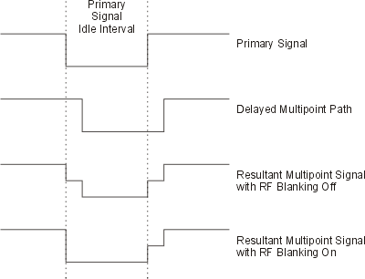
When enabling multipath configuration, it is best to turn off RF Blanking. Leaving Blanking on can result in partial blanking of any delayed multipaths (see the figure below). To disable RF Blanking, click the in the tree view and set the RF Blanking to None. You can also turn off RF blanking on the signal generator after the waveform file has been downloaded.

Effect of RF blanking on signals with multipoint reflection